




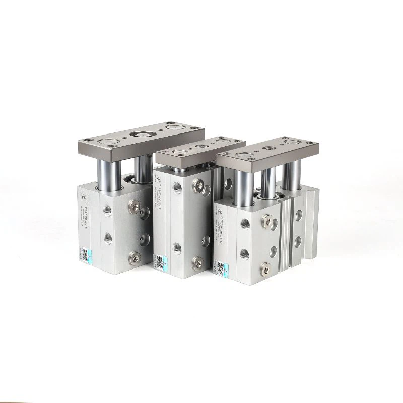
Slide Bearing Guide Cylinder
TCL triple rod pneumatic cylinders use a three-rod guide structure for maximum rigidity and anti-rotation performance in short-stroke precision applications. Bore Ø6–Ø100mm, stroke 5–250mm.

- Product Introduction

When Two Guide Rods Still Aren't Enough Rigidity
A dual guide rod cylinder solves rotation and side-load problems for most guided applications - but in short-stroke, high-precision tasks where the load is heavy, off-center, or the positioning tolerance is especially tight, even two rods can allow a small amount of twist or deflection under load. That small margin is exactly what a triple rod structure is built to close.
The XCTCL series adds a third guide rod to the standard dual-rod configuration, distributing torque and side load across three resistance points instead of two. The tradeoff is stroke range: XCTCL is built for short, precise movements (5–250 mm) rather than long-travel applications, trading reach for maximum rigidity within that shorter range.
It's the option to reach for when a guided cylinder needs to hold tight positioning tolerance under heavy or uneven loading, and the required stroke is short enough that the triple-rod footprint isn't a constraint.
TCL VS MGP - Which Guided Cylinder to Choose
Both series build guiding directly into the cylinder to resist rotation and side load, but they're suited to different jobs:
| Series | Guide Structure | Best Suited For |
|---|---|---|
| MGP | Dual guide rod | General guided applications across a wide stroke range, where standard anti-rotation and side-load resistance is enough |
| TCL | Triple guide rod | Short-stroke (5–250 mm) applications needing maximum rigidity - heavy or off-center loads, tight positioning tolerance |
If the application needs a longer stroke or standard-duty guiding, MGP is usually the simpler and more economical choice. If the stroke is short and the load is heavy, off-center, or the tolerance is unusually tight, the third guide rod on XCTCL earns its place.
What the Triple Rod Structure Changes
- Torque and side load split across three resistance points instead of two. Adding a third rod reduces the load each individual rod has to resist, which keeps rotation and deflection controlled even under heavier or more uneven loading than a dual-rod design is rated for.
- Positioning accuracy holds up over repeated heavy-load cycles. Because no single rod is carrying a disproportionate share of the load, repeatability degrades more slowly over the equipment's service life - relevant for clamping and fixture applications that run the same heavy cycle thousands of times.
- Guide and drive functions are combined in one unit. As with other guided cylinder series, XCTCL eliminates the need for a separate external guide rail, cutting both parts count and alignment work during installation.
- Multiple mounting orientations fit different machine layouts. Bottom, side, and top mounting options are available, so the cylinder can be installed to match existing equipment structure rather than forcing a redesign around it.
Technical Specifications
| Specification | Details |
|---|---|
| Product Series | XCTCL / XCTCM |
| Product Type | Triple rod guided pneumatic cylinder |
| Cylinder Bore | Ø6 / Ø10 / Ø16 / Ø20 / Ø25 / Ø32 / Ø40 / Ø50 / Ø63 / Ø80 / Ø100 mm |
| Working Medium | Filtered compressed air |
| Operating Pressure | 0.15–0.7 MPa |
| Maximum Pressure | 1.05 MPa |
| Working Temperature | -20°C to 70°C |
| Speed Range | 50–500 mm/s |
| Stroke Range | 5–250 mm |
| Cushion Type | Rubber buffer |
| Sensor Option | DMSG, CMS |
Where XCTCL Is Typically Used
- Industrial automation - assembly machines, pick-and-place systems, and positioning equipment where repeatability under heavy load matters.
- Electronics manufacturing - PCB assembly, semiconductor equipment, and inspection machines requiring tight, twist-free positioning.
- Packaging machinery - feeding systems, sorting machines, and material handling running sustained cycle counts.
- Precision machinery - fixture positioning, clamping systems, and linear motion control where off-center loading is routine.
How to Select an XCTCL Cylinder
- Bore size - eleven options from Ø6 to Ø100 mm; larger bores suit heavier loads and higher torque requirements.
- Stroke length - select within the 5–250 mm range based on required travel distance; for longer strokes, MGP's dual guide rod structure is the better starting point.
- Mounting method - top, bottom, or side mounting, chosen to match your existing equipment structure.
- Sensor requirement - specify a magnetic switch configuration if position detection is needed.
If you're unsure which bore or guide structure fits your load and tolerance requirements, share your load weight, stroke, and positioning tolerance and the right configuration can be confirmed directly.
Frequently Asked Questions
1.What is a triple rod pneumatic cylinder?
A guided pneumatic actuator with three guide rods instead of the standard two, built for maximum rigidity, anti-rotation performance, and precise positioning under heavier or off-center loads.
2.How is TCL different from a dual guide rod cylinder like MGP?
The third guide rod splits torque and side load across three resistance points rather than two, which holds tighter tolerance under heavier or more uneven loading. The tradeoff is stroke range - TCL covers 5–250 mm, while MGP supports a wider stroke range for general guided applications.
3.What load conditions call for triple rod guiding instead of dual rod?
Heavy off-center loads, tight repeatability requirements over high cycle counts, or applications where a dual-rod cylinder has shown measurable deflection under the actual working load are the typical triggers for stepping up to a triple rod structure.
4.What bore sizes are available?
Eleven standard bores from Ø6 to Ø100 mm, covering light positioning tasks through heavy industrial loads.
5.Can TCL cylinders be customized?
Yes - stroke length (within the standard range), mounting orientation, and sensor configuration can all be specified to match your equipment requirements.
Designation and Model Numbering System


Standard Specifications
|
Bore size (mm) |
6 |
10 |
12 |
16 |
20 |
25 |
32 |
40 |
50 |
63 |
80 |
100 |
|
|
Action type |
Double-acting |
||||||||||||
|
Working medium |
Air (filtered through a 40μm or finer filter) |
||||||||||||
|
Operating pressure range |
0.15~0.7MPa(23~100psi) |
0.1~1.0MPa(14~145psi) |
|||||||||||
|
Proof pressure |
1.05MPa(152psi) |
1.5MPa(215psi) |
|||||||||||
|
Operating temperature |
-20~70℃ |
||||||||||||
|
Operating speed range |
50~500mm/s |
30~500mm/s |
50~400mm/s |
||||||||||
|
Stroke tolerance |
 |
||||||||||||
|
Cushion type |
Shock Absorber Pad | ||||||||||||
|
Non-rotating accuracy ① |
Linear bearing |
- |
±0.08° |
±0.07° |
±0.06° |
±0.05° |
±0.04° |
||||||
|
Bronze bushing |
±1.0° |
±0.10° |
±0.09° |
±0.08° |
±0.06° |
±0.05° |
|||||||
|
Port size ② |
M3 x 0.05 |
M5 x 0.8 |
PT1/8 |
PT1/4 |
PT3/8 |
||||||||
|
Magnetic switch |
DMSG,CMSG,EMSG |
||||||||||||
① Non-rotating accuracy refers to the angle of rotation of the cylinder mounting plate when the cylinder is fully retracted;
② Port thread options include G and NPT; Note: XCTC series models are fully equipped with magnets.
stroke

Note: Non-standard stroke cylinders with a stroke differing from the standard by 1–5 mm are modified from the next larger standard-stroke cylinder and share the same external dimensions.
For example, a cylinder with an 86 mm stroke is modified from a standard 90 mm stroke cylinder and retains the same external dimensions;
however, a cylinder with an 84 mm stroke differs from the next larger standard stroke (90 mm) by 6 mm, so it must be ordered as a non- standard item.
Fastening method


|
Bore / Symbol |
A |
D(Min) |
|
|
TCM |
TCL |
||
|
6 |
20.5 |
Not required |
- |
|
10 |
23 |
Not required |
- |
|
12 |
41 |
8 |
|
|
16 |
46 |
10 |
|
|
20 |
54 |
12 |
|
|
25 |
64 |
14 |
|
|
32 |
78 |
18 |
|
|
40 |
86 |
18 |
|
|
50 |
110 |
22 |
|
|
63 |
124 |
22 |
|
|
80 |
156 |
30 |
25 |
|
100 |
188 |
32 |
30 |
Allowable load torque
|
Bore Size |
Model Type |
stroke(mm) | |||||||||||||||||||
|
5 |
10 |
15 |
20 |
25 |
30 |
40 |
50 |
60 |
70 |
75 |
80 |
90 |
100 |
125 |
150 |
175 |
200 |
225 |
250 |
||
| Maximum permissible lateral load | |||||||||||||||||||||
|
|
|||||||||||||||||||||
|
12 |
TCM |
- |
44 |
- |
33 |
29 |
26 |
41 |
36 |
30 |
28 |
26 |
25 |
24 |
22 |
19 |
17 |
- |
- |
- |
- |
|
TCL |
- |
37 |
- |
27 |
25 |
22 |
35 |
30 |
27 |
24 |
23 |
21 |
19 |
18 |
15 |
12 |
- |
- |
- |
- |
|
|
16 |
TCM |
- |
67 |
- |
51 |
42 |
37 |
63 |
58 |
49 |
41 |
37 |
35 |
33 |
32 |
27 |
24 |
22 |
20 |
- |
- |
|
TCL |
- |
54 |
- |
40 |
37 |
32 |
54 |
47 |
42 |
38 |
35 |
32 |
30 |
28 |
23 |
20 |
17 |
15 |
- |
- |
|
|
20 |
TCM |
- |
- |
- |
78 |
61 |
57 |
123 |
112 |
99 |
91 |
67 |
84 |
79 |
75 |
66 |
59 |
54 |
49 |
45 |
42 |
|
TCL |
- |
- |
- |
58 |
52 |
48 |
101 |
90 |
83 |
74 |
70 |
69 |
63 |
58 |
62 |
54 |
48 |
43 |
39 |
35 |
|
|
25 |
TCM |
- |
- |
- |
93 |
89 |
76 |
142 |
131 |
119 |
107 |
101 |
97 |
90 |
85 |
68 |
79 |
71 |
65 |
61 |
55 |
|
TCL |
- |
- |
- |
82 |
79 |
68 |
132 |
118 |
109 |
99 |
93 |
88 |
81 |
77 |
80 |
70 |
62 |
55 |
50 |
45 |
|
|
32 |
TCM |
- |
- |
- |
- |
203 |
190 |
179 |
164 |
221 |
197 |
182 |
172 |
163 |
157 |
142 |
127 |
116 |
106 |
98 |
91 |
|
TCL |
- |
- |
- |
- |
191 |
182 |
166 |
157 |
207 |
178 |
164 |
156 |
150 |
144 |
203 |
186 |
171 |
158 |
146 |
137 |
|
|
40 |
TCM |
- |
- |
- |
- |
203 |
190 |
179 |
164 |
221 |
197 |
182 |
172 |
163 |
159 |
142 |
127 |
116 |
106 |
97 |
91 |
|
TCL |
- |
- |
- |
- |
190 |
182 |
166 |
157 |
210 |
179 |
163 |
156 |
150 |
144 |
203 |
185 |
171 |
158 |
146 |
137 |
|
|
50 |
TCM |
- |
- |
- |
- |
296 |
283 |
268 |
245 |
303 |
288 |
273 |
266 |
253 |
241 |
216 |
195 |
179 |
164 |
155 |
142 |
|
TCL |
- |
- |
- |
- |
208 |
196 |
185 |
173 |
259 |
232 |
223 |
212 |
207 |
199 |
264 |
242 |
224 |
207 |
195 |
181 |
|
|
63 |
TCM |
- |
- |
- |
- |
296 |
283 |
268 |
245 |
303 |
288 |
273 |
266 |
253 |
241 |
216 |
195 |
179 |
164 |
153 |
142 |
|
TCL |
- |
- |
- |
- |
206 |
196 |
180 |
171 |
259 |
232 |
221 |
212 |
205 |
196 |
262 |
240 |
221 |
205 |
191 |
178 |
|
| Maximum permissible torque | |||||||||||||||||||||
|
|
|||||||||||||||||||||


|
12 |
TCM |
- |
0.90 |
- |
0.79 |
0.71 |
0.65 |
0.77 |
0.72 |
0.65 |
0.53 |
0.50 |
0.47 |
0.41 |
0.36 |
0.31 |
0.27 |
- |
- |
- |
- |
|
TCL |
- |
0.61 |
- |
0.45 |
0.40 |
0.35 |
0.58 |
0.50 |
0.44 |
0.39 |
0.37 |
0.35 |
0.32 |
0.29 |
0.24 |
0.20 |
- |
- |
- |
- |
|
|
16 |
TCM |
- |
1.21 |
- |
1.04 |
0.94 |
0.88 |
1.23 |
1.11 |
0.99 |
0.72 |
0.69 |
0.65 |
0.61 |
0.58 |
0.50 |
0.44 |
0.40 |
0.36 |
- |
- |
|
TCL |
- |
0.99 |
- |
0.74 |
0.66 |
0.59 |
0.99 |
0.86 |
0.77 |
0.69 |
0.65 |
0.61 |
0.57 |
0.52 |
0.43 |
0.37 |
0.32 |
0.28 |
- |
- |
|
|
20 |
TCM |
- |
- |
- |
1.57 |
1.42 |
1.31 |
2.39 |
2.15 |
1.97 |
1.90 |
1.88 |
1.86 |
1.72 |
1.63 |
1.44 |
1.28 |
1.16 |
1.06 |
1.01 |
0.90 |
|
TCL |
- |
- |
- |
1.26 |
1.14 |
1.03 |
2.17 |
1.94 |
1.79 |
1.59 |
1.52 |
1.46 |
1.33 |
1.25 |
1.34 |
1.17 |
1.03 |
0.93 |
0.88 |
0.76 |
|
|
25 |
TCM |
- |
- |
- |
2.40 |
2.22 |
2.01 |
3.66 |
3.35 |
3.17 |
3.06 |
2.96 |
2.91 |
2.77 |
2.57 |
2.26 |
2.02 |
1.83 |
1.67 |
1.57 |
1.42 |
|
TCL |
- |
- |
- |
2.11 |
1.96 |
1.75 |
3.37 |
3.02 |
2.71 |
2.42 |
2.38 |
2.33 |
2.19 |
1.97 |
2.05 |
1.78 |
1.58 |
1.41 |
1.22 |
1.16 |
|
|
32 |
TCM |
- |
- |
- |
- |
6.35 |
6.00 |
5.73 |
5.13 |
5.98 |
5.74 |
5.69 |
5.62 |
5.11 |
4.97 |
4.42 |
3.98 |
3.61 |
3.31 |
2.97 |
2.84 |
|
TCL |
- |
- |
- |
- |
5.95 |
5.73 |
5.11 |
4.89 |
5.43 |
5.15 |
5.11 |
5.02 |
4.70 |
4.51 |
6.34 |
5.79 |
5.33 |
4.93 |
4.33 |
4.29 |
|
|
40 |
TCM |
- |
- |
- |
- |
7.00 |
6.60 |
6.11 |
5.66 |
6.66 |
6.31 |
6.27 |
6.23 |
5.86 |
5.48 |
4.78 |
4.38 |
3.98 |
3.65 |
3.34 |
3.13 |
|
TCL |
- |
- |
- |
- |
6.55 |
6.21 |
5.77 |
5.39 |
6.17 |
5.67 |
5.62 |
5.58 |
5.33 |
4.96 |
6.98 |
6.38 |
5.87 |
5.43 |
5.00 |
4.72 |
|
|
50 |
TCM |
- |
- |
- |
- |
13.00 |
12.60 |
11.00 |
10.80 |
13.70 |
12.70 |
12.00 |
11.80 |
11.10 |
10.80 |
9.50 |
8.60 |
7.86 |
7.24 |
6.80 |
6.24 |
|
TCL |
- |
- |
- |
- |
9.17 |
8.75 |
8.30 |
7.62 |
10.30 |
9.94 |
9.83 |
9.77 |
8.82 |
8.74 |
11.60 |
10.70 |
9.83 |
9.12 |
8.95 |
7.95 |
|
|
63 |
TCM |
- |
- |
- |
- |
14.70 |
13.60 |
12.90 |
12.10 |
19.40 |
16.20 |
13.50 |
12.70 |
12.10 |
11.90 |
10.70 |
9.69 |
8.86 |
8.16 |
7.52 |
7.04 |
|
TCL |
- |
- |
- |
- |
10.20 |
9.74 |
9.20 |
8.48 |
17.50 |
14.00 |
11.00 |
10.60 |
10.20 |
9.74 |
13.00 |
11.90 |
11.00 |
10.20 |
9.63 |
8.84 |
|
|
80 |
TCM |
- |
- |
- |
- |
21.9 |
- |
- |
18.6 |
- |
- |
22.9 |
- |
- |
20.5 |
18.6 |
17 |
15.6 |
14.5 |
- |
12.6 |
|
TCL |
- |
- |
- |
- |
15.1 |
- |
- |
23.3 |
- |
- |
22.7 |
- |
- |
20.6 |
18.9 |
17.3 |
16 |
14.8 |
- |
12.9 |
|
|
100 |
TCM |
- |
- |
- |
- |
38.8 |
- |
- |
33.5 |
- |
- |
37.5 |
- |
- |
33.8 |
30.9 |
28.4 |
26.2 |
24.4 |
- |
21.4 |
|
TCL |
- |
- |
- |
- |
27.1 |
- |
- |
30.6 |
- |
- |
37.5 |
- |
- |
34.6 |
31.8 |
29.3 |
27.2 |
25.3 |
- |
22.1 |
Internal structure


Outline Dimensions (mm)


Hot Tags: slide bearing guide cylinder, China slide bearing guide cylinder manufacturers, suppliers, factory, air piston cylinder, pneumatic valve double acting, Guided Compact Pneumatic Cylinder, Aluminium Guided Air Cylinder, 2 air cylinder, Slide Bearing Guide Cylinder


